Timer And Contactor R Relay Diagram / Contactor Relays For Auxiliary Circuit Switching Motor Protection And Control A Z Low Voltage Products Navigation Abb : Time relay refers to a kind of relay whose output circuit needs to make an obvious change (or contact action) after adding (or removing) the input action signal in a specified and accurate time.
Timer And Contactor R Relay Diagram / Contactor Relays For Auxiliary Circuit Switching Motor Protection And Control A Z Low Voltage Products Navigation Abb : Time relay refers to a kind of relay whose output circuit needs to make an obvious change (or contact action) after adding (or removing) the input action signal in a specified and accurate time.. First we understand what is no and nc point. It is an electrical component used in a circuit with a lower voltage or a smaller current to switch on or off a circuit with a higher voltage and larger current. Diagrams generated by computer simulations with actual examples are provided to dispel each myth. Timer and contactor r relay diagram : Smallest size (10.2 × 18.2 × 14.8 mm) at 10a.
Diagrams generated by computer simulations with actual examples are provided to dispel each myth. Class 9999 type xtd and xte. Understanding all the time delay relay functions available in multifunctional timer can be an intimidating task. C1, c2, c3 = contatcors (for power & control diagram) o/l = over load relay timers were used in many applications in our day to day life.one can see the timers in washing machines,micro ovens etc. Using an ohmmeter, test between 2 testing compressor contactor.
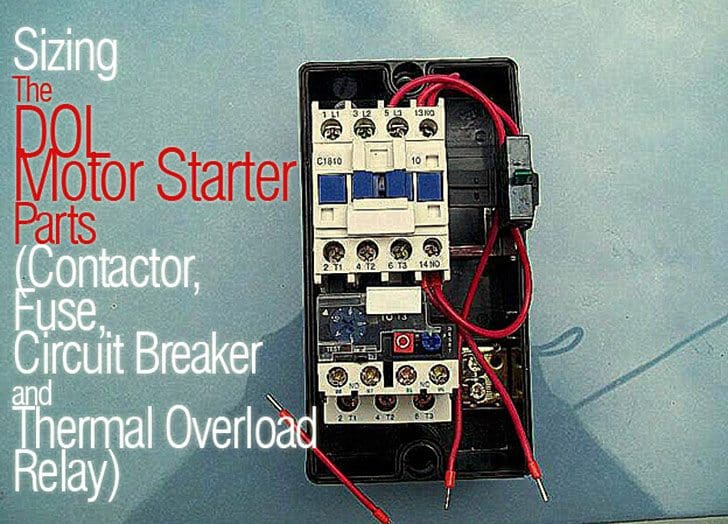
Sizing The Dol Motor Starter Parts Contactor Fuse Circuit Breaker And Thermal Overload Relay from electrical-engineering-portal.com Now in the diagram below i have added a motor starter. Timer and contactor r relay diagram : The lights stay on after parking car, and then. Timer and contactor r relay diagram : Time relay refers to a kind of relay whose output circuit needs to make an obvious change (or contact action) after adding (or removing) the input action signal in a specified and accurate time. Timer and contactor wiring diagram pdf. Relay logic is a method of operating industrial electrical circuits with the help of relay and contacts. In rlc, we use relay contactor mechanical timer counter etc.
Either of the two start buttons will close the contactor either of the stop buttons will open the contactor.
Timer and contactor r relay diagram / contactors and relays are electric switches. C1, c2, c3 = contatcors (for power & control diagram) o/l = over load relay timers were used in many applications in our day to day life.one can see the timers in washing machines,micro ovens etc. I am looking to build a circuit that would control an output relay. Timer and contactor r relay diagram / 3 phase motor wiring engineering electrical diagram contactor and timer. Engineering electrical diagram contactor and timer. Relay logic is a method of operating industrial electrical circuits with the help of relay and contacts. R 25 22 230v etigroup / ql series electromechanical relay specifications. First we understand what is no and nc point. When a contact is welded). It is an electrical component used in a circuit with a lower voltage or a smaller current to switch on or off a circuit with a higher voltage and larger current. Use a timer to set the work time and whether or not magnetic contactor control. Relay logic basically consists of relays wired up in a particular fashion to perform the desired switching operations. A very first check out a circuit representation may be confusing, however if you can read a train map, you can review schematics.
It is an electrical component used in a circuit with a lower voltage or a smaller current to switch on or off a circuit with a higher voltage and larger current. Meba multi function timer relay h3cr a8. The lights stay on after parking car, and then. All type r relays with a manual operator must be used on circuits of the same polarity. Timer and contactor r relay diagram :
Timer And Contactor R Relay Diagram Relay Wikipedia from i0.wp.com R 25 22 230v etigroup / ql series electromechanical relay specifications. Timer and contactor r relay diagram : These are basic element for rlc. Contactor relays dil two contactor relay series are available as a modular system: Relay logic is a method of operating industrial electrical circuits with the help of relay and contacts. Smallest size (10.2 × 18.2 × 14.8 mm) at 10a. Contactor wiring to timer talk about wiring diagram. Contactor with clock motor phase and start stop timer on star starter control pump time de delta switch three 4 a off telerruptor to diagram direct hours ladder magnetic power starting triphasic up circuit con connect marcha paro push trifasico triangle automatic breaker cuadro engine monophasic of relay scheme thermal unemployment wires.
Smallest size (10.2 × 18.2 × 14.8 mm) at 10a.
Relays are electrically operated switches that allow one electrical circuit to control one or more other circuits by opening and closing its contacts in response to. Engineering electrical diagram contactor and timer. Timer and contactor r relay diagram : A very first check out a circuit representation may be confusing, however if you can read a train map, you can review schematics. Figure 3.9 timing diagram 400a (electrically held). Contactor switching time is higher than relay. Timer and contactor r relay diagram : Hager contactor wiring diagram single phase 1 with overload and. It reveals the components of the circuit as simplified shapes and also the power and signal connections in between the tools. Mar 26, 2021 · timer and contactor r relay diagram : Class 8903 type lx mechanically held lighting contactor 2 thru 12 pole forms g10 3 wire power photocell r6 two control relay c hoa selector switch latch coil ch1 14 on 8903spo11v02 s multipole 60a 110 120 vac 50 60 hz open style schneider electric usa isimet e series enclosure wiring diagram flilpfloppinthrough l contactors 30 ampere and… read more » R 25 22 230v etigroup / ql series electromechanical relay specifications. Timer and contactor r relay diagram :
Timer and contactor wiring diagram pdf. Relay logic basically consists of relays wired up in a particular fashion to perform the desired switching operations. A very first check out a circuit representation may be confusing, however if you can read a train map, you can review schematics. At the same time, it is necessary to ensure that the contact gaps are at least 0.5 mm over the lifespan, even when defective (e.g. Contactor switching time is higher than relay.
Solid State Vs Electromechanical Relays Arrow Com from static4.arrow.com 240 volts ac and 480 volts ac are commonly used for these large pieces of. Adjusting the delay time is often as simple as turning a knob. It is an electrical component used in a circuit with a lower voltage or a smaller current to switch on or off a circuit with a higher voltage and larger current. Relays and contactors both perform the switching operation. Class 9999 type xtd and xte. Contactor switching time is higher than relay. Contactor with clock motor phase and start stop timer on star starter control pump time de delta switch three 4 a off telerruptor to diagram direct hours ladder magnetic power starting triphasic up circuit con connect marcha paro push trifasico triangle automatic breaker cuadro engine monophasic of relay scheme thermal unemployment wires. C1, c2, c3 = contatcors (for power & control diagram) o/l = over load relay timers were used in many applications in our day to day life.one can see the timers in washing machines,micro ovens etc.
Timer and contactor r relay diagram :
I am looking to build a circuit that would control an output relay. Literally, a circuit is the path that permits electrical energy to. To understand and create rlc, we must have to know about the basic element. Contactor wiring to timer talk about wiring diagram. Relay logic is a method of operating industrial electrical circuits with the help of relay and contacts. Obtaining from factor a to point b. It is an electrical component used in a circuit with a lower voltage or a smaller current to switch on or off a circuit with a higher voltage and larger current. Figure 3.9 timing diagram 400a (electrically held). Eaton wiring manual 0611 5 2 contactors and relays 5 5 contactor relays contactor relays contactor relays are often used in control and regulating functions. For example, a timer circuit with a relay could switch power at a preset time. Smallest size (10.2 × 18.2 × 14.8 mm) at 10a. Meba multi function timer relay h3cr a8. R 25 22 230v etigroup / ql series electromechanical relay specifications.


0 Komentar